Resistor Capacitor Interaction
As you begin your study of electronics, you will find reams of information about Ohm’s law, Kirchhoff’s law, etc. While it’s fun to figure out the right resistor to pair with an LED for your first Blinking LED, it gets more interesting when you start looking at the interactions between different components.
This article will explore the interactions between resistors and capacitors. For the reader who has never studied either component, the bare minimum you need to know to understand this article is:
- A resistor resists the flow of electricity.
- A capacitor collects electric charge.
- The values of the interacting capacitor and resistor determine how fast the capacitor charges or discharges.
We’ll use the schematic below to describe the interaction.
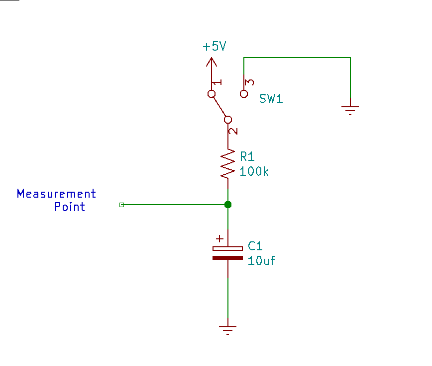
When the switch is in position 1 - 2, 5 volts (the 5V in the schematic) is applied to the resistor R1. R1 will allow a limited amount of current to pass, which will charge the capacitor C1 up to 5 volts over time.
When the switch is in position 1 - 3, 0 volts (funny ground symbol to the right is 0 volts) is applied to the resistor R1. If the Capacitor C1 is charged, it will discharge through the resistor over time.
We can measure these changes at the Measurement Point, and we’ll use an Arduino to do so! Setting up the hardware will be the easy part, so let’s focus on that first. The components you will need to gather are:
- a 100k resistor. You’ll need to study resistor color codes to pick the right resistor. If you bought an Arduino starter kit, the resistors may already be labeled on the tape. Try to pick a resistor with nice long leads if you don’t have a breadboard.
- a 10 uf capacitor. The capacitor you are looking for is an aluminum can with 2 legs. The value will be written on the side, and it will be marked with a
-for the negative lead. - a breadboard and some jumper wires will be helpful but not absolutely necessary.
And now to wire everything up!
- Connect the negative lead of the capacitor to
GNDand the positive lead toA0. Take care not to attach the negative lead to the nearbyVin. - Connect one end of the resistor to
A0and the other end to pin8which is across the board fromA0. This is going to be a stretch. You may need a breadboard and jumpers to accomplish this.
That’s it. the circuit is wired up! Now we need to talk about the program we are going to use to control this circuit. You may want to familiarize yourself with some basic tutorials from arduino.cc before getting into this. I’ll try to describe what is happening in as much detail as I can. Let’s step through the program.
Any line starting with // is a comment and is ignored when building the program. Do your future self a favor and comment your code. I probably comment too little. Below is a sample of the commentary at the beginning of the program.
// Exploring RC time constant.
// Connections:
// A0 attached to the positive side of 10uf capacitor.
// Negative side of 10uf capacitor attached to ground.
.
.
.
The #define statements below are text replacements. For example, any time the build process sees CHARGEPIN it will replace it with 8. CHARGEPIN will emulate the switch in the schematic above. CHARGEREAD will be our Measureing Point from the schematic, and DELAY will be the amount of time between measurements.
#define CHARGEPIN 8
#define CHARGEREAD A0
#define DELAY 100
The Setup function below will run once when the Arduino starts. We set the CHARGEPIN to OUTPUT mode so that we can change its voltage, and we use Serial.begin to setup communications between the arduino and computer so we can plot pretty graphs.
void setup() {
  pinMode(CHARGEPIN, OUTPUT);
  Serial.begin(115200);
}
Anything in the loop function will run over and over until the Arduino is powered down. This means the Arduino will step through every statement in the function, and then start at the top of the loop again.
void loop() {
charge is the variable we’ll use to store our measurement from the A0 pin.
int charge = 0;
Below, we print to the serial line, alerting that we are setting CHARGEPIN to 0 volts (low). The digitalWrite statement actually sets CHARGEPIN to 0 volts.
  // set the CHARGEPIN low to discharge capacitor.
  Serial.println("Setting_Charge_LOW");
  digitalWrite(CHARGEPIN, LOW);
The for loop below runs 50 times. Inside the loop, we are reading the voltage on the A0 pin with analogRead. The charge variable stores this value. We then print the charge value to serial so we can inspect it on our computer. We delay 100ms before continuing with the loop. Overall, the loop will run for about 5 seconds. \( 50 loops * 100 milliseconds / 1000 = 5seconds \)
  for (int i=0; i<50; i++){
    charge = analogRead(CHARGEREAD);
    Serial.println(charge);
    delay(DELAY);
  }
Below, we set the CHARGEPIN to 5 volts (HIGH), and as in the above for loop, we measure the A0 pin 50 times over 5 seconds and send the results through the serial port, to the computer.
  // set the CHARGEPIN high to charge capacitor.
  Serial.println("Setting_Charge_HIGH");
  digitalWrite(CHARGEPIN, HIGH);
  for (int i=0; i<50; i++){
    charge = analogRead(CHARGEREAD);
    Serial.println(charge);
    delay(DELAY);
  }
}
As a reminder, when we come to the end of the loop function, the Arduino will just go back to the top of the loop and run all of the code again.
Run all of this code on the Arduino and see what happens:
- Start a new sketch (call it something like
rc-time). - Copy the code at the end of this article into the sketch and save it.
- Connect your Arduino to the PC.
- Under
ToolsselectSerial Plotter. Set thebaudin the lower left to115200 baud. - Compile and upload the sketch.
After the sketch is uploaded, you should see a graph start to draw over a minute that looks like this:
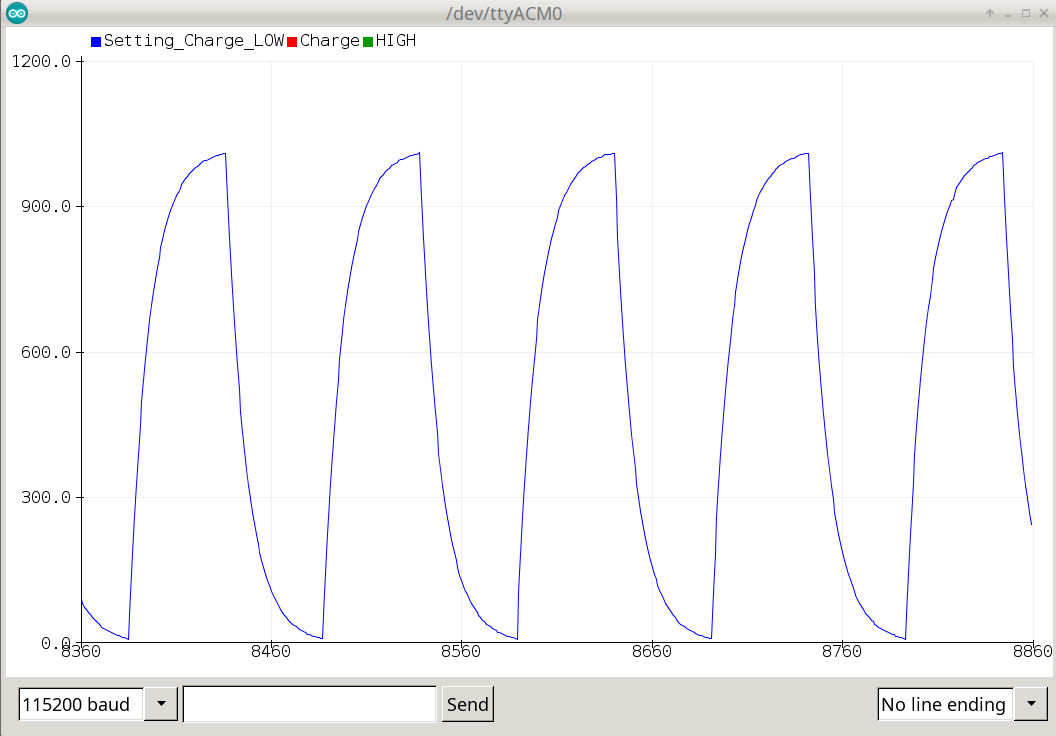
What we’re seeing in this graph is the RC time constant in action. When we set the CHARGEPIN high, The capacitor will charge over time based on the values of the capacitor and the resistor. Similarly, when we set CHARGEPIN low, eventually the capacitor will discharge. resistance in ohms * capacitance in farads = time in seconds
The larger the capacitor or resistor values, the slower the charge rate. The lower the capacitor or resistor values, the faster the charge rate. If you multiply our resistor value (100,000 ohms) with our capacitor value (0.00001 Farads, or 10 microfarads), you’ll get 1 second (the RC time constant with these values). After 5 time constants (5 seconds in this case), the capacitor is mostly charged or discharged.
The interaction between resistors and capacitors is a basic building block in electronics. It’s used in filters, oscillators, and timers. When you start using the 555 Timer, you will encounter a lot of interacting resistors and capacitors.
We’ve come to the end of the curated exercise. To explore the RC time constant further, use different values for the resistor and capacitor. What happens when you use a 20uf capacitor? How about 5uf? Change the resistor value to 56k ohms. Change the resistor to 200k ohms. For some real fun, try to attach a 100k potentiometer and a 10k resistor in series with the capacitor and adjust the potentiometer. Watch what happens to our graph over time.
If you drastically change the values of the resistor and capacitor to 10x more or less, you may need to change the DELAY defined in the program to some much larger or smaller to see the pretty graphs we are seeing with the beginning values.
Source for the RC time schetch in full below
// Exploring RC time constant.
// Connections:
// A0 attached to the positive side of 10uf capacitor.
// Negative side of 10uf capacitor attached to ground.
// A0 attached to 100k resistor.
// 8 attached to other side of 100k resistor.
//
// The goal here is to toggle the charge pin to ground,
// read the value many times over a few seconds,
// toggle the charge pin high,
// read the value many times over a few more seconds,
// repeat.

#define CHARGEPIN 8
#define CHARGEREAD A0
#define DELAY 100

void setup() {
  pinMode(CHARGEPIN, OUTPUT);
  Serial.begin(115200);
}

void loop() {
  int charge = 0;
  // set the CHARGEPIN low to discharge capacitor.
  Serial.println("Setting_Charge_LOW");
  digitalWrite(CHARGEPIN, LOW);
  for (int i=0; i<50; i++){
    charge = analogRead(CHARGEREAD);
    Serial.println(charge);
    delay(DELAY);
  }
  // set the CHARGEPIN high to charge capacitor.
  Serial.println("Setting_Charge_HIGH");
  digitalWrite(CHARGEPIN, HIGH);
  for (int i=0; i<50; i++){
    charge = analogRead(CHARGEREAD);
    Serial.println(charge);
    delay(DELAY);
  }
}